Jagged Arcs/Circles

If you have a question about the software please ask it here.

Jagged Arcs/Circles

Postby tedris » Wed Mar 02, 2022 10:39 am

Hi there,

i got a problem with my CNC running an ETH300 5LPT.

Circles/Arcs or non linear (combination of X and Y) movements seem to be very rough.
I use Fusion as a CAM software and tried the following so far:

in UCCNC:
Constant Velocity Mode ON/OFF
Acceleration of X and Y up to 1800mm\s2

in Fusion:
Smoothing enabled: Tolerance and Smoothing both at 0.05mm at the moment (to generate less lines of code and starve the controller)
Deactivated IJK mode in the Postprocessor so i only get polylines

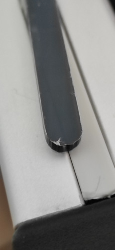
Nothing seem to help with the issue, see the picture of a Part i routed.
Image
tedris
 
Posts: 6
Joined: Wed Mar 02, 2022 10:32 am

Re: Jagged Arcs/Circles

Postby ger21 » Wed Mar 02, 2022 12:02 pm

In UCCNC, turn CV on, and increase the error tolerance settings.
However, it look to me like there may be some mechanical issues, as the cut is not very uniform.
Gerry
UCCNC 2022 Screenset - http://www.thecncwoodworker.com/2022.html
ger21
 
Posts: 2714
Joined: Sat Sep 03, 2016 2:17 am

Re: Jagged Arcs/Circles

Postby tedris » Wed Mar 02, 2022 12:16 pm

The Constant Velocity is on as i wrote in my OP.

I cant confirm nor deny if there is a mechanical issue. To me it seems as if not but i wanted to search for software issues first, since i read a lot about uccnc problems with arcs and such.
I have no issues with linear cutting moves (for example when i cut out a square contour as a test). The problems only occure when both axis are moving at the same time.
tedris
 
Posts: 6
Joined: Wed Mar 02, 2022 10:32 am

Re: Jagged Arcs/Circles

Postby ger21 » Wed Mar 02, 2022 1:43 pm

You need to adjust the CV settings, until it cuts the arcs properly.
Gerry
UCCNC 2022 Screenset - http://www.thecncwoodworker.com/2022.html
ger21
 
Posts: 2714
Joined: Sat Sep 03, 2016 2:17 am

Re: Jagged Arcs/Circles

Postby tedris » Wed Mar 02, 2022 2:55 pm

I dont really get what you are saying.
I only see a checkbox for constant velocity, nothing can be adjusted.

Maybe i am missing something?

Would you recommend letting UCCNC using G2/G3 Gcode or would you recommend only polylines instead?
tedris
 
Posts: 6
Joined: Wed Mar 02, 2022 10:32 am

Re: Jagged Arcs/Circles

Postby hmnijp » Wed Mar 02, 2022 3:25 pm

tedris wrote:I dont really get what you are saying.
I only see a checkbox for constant velocity, nothing can be adjusted.
Maybe i am missing something?
Would you recommend letting UCCNC using G2/G3 Gcode or would you recommend only polylines instead?


There are no serious problems with the arcs. There is a problem with the fact that people do not understand how to configure the CV for their tasks.

These settings, they affect the operation of the CV. you can read about them in the manual. You can try to install the same. If you do not need serious accuracy, you can increase the error value.
2022-03-02 19-10-19 UCCNC software   Running in demo mode....jpg


or here is a little explanation and practice of use.
viewtopic.php?p=26223#p26223

I am using fusion360. I recommend using arcs, but the postprocessor setting "minimum chord length" = 0.1-0.2mm. - this will remove many small arcs.
hmnijp
 
Posts: 44
Joined: Sun Jan 17, 2021 12:59 am

Re: Jagged Arcs/Circles

Postby tedris » Thu Mar 03, 2022 7:59 am

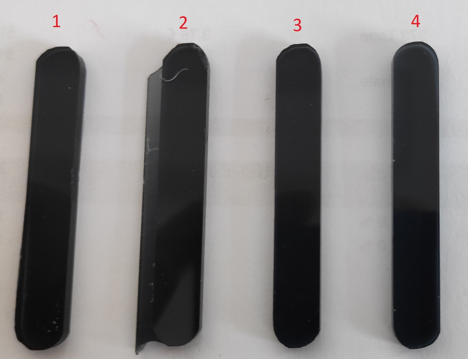
I set all the CV settings as in your picture except for arc radius tolerance and linear error max, which i set to 0.1.

See picture fo results
Image
1: My previous result (1500mm/min Feedrate)
2: same G-Code with polylines with new CV settings (1500mm/min Feedrate)
3: G-Code with IJK (G2/G3) new CV settings (1500mm/min Feedrate)
4: G-Code with IJK (G2/G3) new CV settings (500mm/min Feedrate)

Samples 1 2 and 3 look very much identical in real life. Sample 4 looks better than the other samples, though far from acceptable for me...Still jagged edges.
The feedrates at 1500mm/min is the calculated and recommended feed from sorotec (acrylic 1 tooth cutting tool)

Im i am not mistaked the fact that lower feedrate shows a better result is telling me that either my accel is too high or i have an mechanical issue. Or am i wrong here?
tedris
 
Posts: 6
Joined: Wed Mar 02, 2022 10:32 am

Re: Jagged Arcs/Circles

Postby ger21 » Thu Mar 03, 2022 12:30 pm

except for arc radius tolerance and linear error max, which i set to 0.1.


Try setting it to a higher value, 0.2, or even 0.5, and see if the result is different.
Gerry
UCCNC 2022 Screenset - http://www.thecncwoodworker.com/2022.html
ger21
 
Posts: 2714
Joined: Sat Sep 03, 2016 2:17 am

Re: Jagged Arcs/Circles

Postby fixebr » Thu Mar 03, 2022 5:05 pm

Can you post the G-Code file with which you get this result?
My English is bad, so you're reading machine translation results. Alas.
User avatar
fixebr
 
Posts: 40
Joined: Thu Dec 30, 2021 8:30 pm
Location: Russia, Moscow

Re: Jagged Arcs/Circles

Postby tedris » Thu Mar 03, 2022 7:17 pm

Code: Select all
(3001)
(F1-Rim-Acryleinsatz)
(T30  D=6. CR=0. - ZMIN=0. - Schaftfraser)
G90
G53 G0 Z0.

(2D-Kontur1)
T30 M6 (Schaftfraser D=6. Sorotec Acryl 1Schneider)
S24000 M3
G64
G54
M8
G43 H30
G0 X3.633 Y12.8
Z18.
Z8.
G1 Z6.1 F500
Y12.624 Z5.676 F500
Y12.2 Z5.5
Y11.6
G3 X4.233 Y11. I0.6 J0.
G1 X49.5 Z3.919 F500
G2 X56.5 Y4. Z3.535 I0. J-7.
X49.5 Y-3. Z3.151 I-7. J0.
G1 X4. Z1.562
G2 X-3. Y4. Z1.178 I0. J7.
X4. Y11. Z0.794 I7. J0.
G1 X26.75 Z0.
X49.5 F1536
G2 X56.5 Y4. I0. J-7.
X49.5 Y-3. I-7. J0.
G1 X4.
G2 X-3. Y4. I0. J7.
X4. Y11. I7. J0.
G1 X26.75
G3 X27.35 Y11.6 I0. J0.6
G1 Y12.2
Y12.624 Z0.176
Y12.8 Z0.6
G0 Z18.
M9
M5
G53 G0 Z0.
M30


Nothing fancy really
tedris
 
Posts: 6
Joined: Wed Mar 02, 2022 10:32 am

Next

Return to Ask a question from support here

Who is online

Users browsing this forum: No registered users and 37 guests