I was going to mention a potentiometer earlier, but did not know your level of knowledge with this stuff.
I'd use something like 1% or better tolerance resistors. If one is 10K make the other one a bit less than 10K.
Let's say the other one was 9.7K for arguments sake. You are 300 ohms away from 10K. So double that and get a 600 ohm 10 turn potentiometer and wire it in series with the 9.7K.
Start of with the potentiometer mid way, i.e. at around 300 ohm, getting the total resistance close to the 10K mark. You then have quite fine adjustment to get the resistances balanced.
Not sure off the top of my head what stock resistance values are available but hopefully the above shows what I mean.
+/-10v to 0-10v
13 posts
• Page 2 of 2 • 1, 2
Re: +/-10v to 0-10v

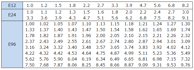
Standard resistance values
The simple way to remember it is E12 is the basic number set,
E24, splits those values in 2 so you have the centre points.
E48 (not shown) splits E24 values in to
E96 splits the E48 values in two.
It is to do with overlaps due to tolerance, so the higher E series are generally of higher tolerance
So E12 is +/-10% tolerance
E24 is +/1 5% tolerance
E48 is +/- 2.5% tolerance
E96 is +/- 1.25% tolerance
So you know they all start at 1 / 100 / 1K / 10K / 100K / 1M
So to work out the E12 series just multiply 1 x 1.2 (+20%) and you get the next value (1.2)
Then 1.2 x 1.2 and you get 1.44....... round up to 1.5..... x 1.2 and you get 1.8 x 1.2 you get 2.16, round up to 2.2.... x 1.2 etc.
E24 just multiply 1.0 x 1.1 to get the next value and so on in the series.
UCCNC Macro Manual v1.2113 - https://drive.google.com/drive/folders/ ... sp=sharing
- Robertspark
- Posts: 1892
- Joined: Sat Sep 03, 2016 4:27 pm
Re: +/-10v to 0-10v
Hello Just typed and killed the whole thing time to do it again.
I have been looking at the resistors I used 10k 5%
I have a 20k 5% ten turn potentiometer I could use this as drawn to balance the circuit.
This would remove creep on the minus side but do nothing on the + side
as they are separate by the relay I would also have to have some adjustment on the + side.
i have drawn this as revision 2 but dont know what to use on the + rail for a pot.
I could just take a stab with one of my 20 turn pots.
i was also thinking since it is a very responsive circuit to begin with. I could put a pull down resistor
after the relay and potentially eliminate the whole resistor change. my problem is creep after all.
Thing is sizing a pull down resistor is not something I know how to do.
I am really leaning toward revision 2 as the circuit is built and it would be the easiest to implement.
Let me know what you think
Thank you
Mark
- mark4
- Posts: 26
- Joined: Tue May 24, 2022 3:55 am
13 posts
• Page 2 of 2 • 1, 2
Return to Ask a question from support here
Who is online
Users browsing this forum: No registered users and 8 guests
